Arduino Tone Matrix
And an overview of the E40M labs of fall quarter
Dec 17, 2025
In fall quarter of sophomore year, I enrolled in ENGR 40M, a class intended to be Stanford's introduction to making in electrical engineering. It lived up to its billing, being not just a crash course in basic circuits and E&M concepts but also an opportunity to build cool circuits of our own in weekly three-hour labs.
For me, these labs were the highlight of the course and quarter. We started off by building a solar-powered USB charger, then a 'useless box' with a motor and switches that would turn itself off when a user turned it on, and even an electrocardiogram (EKG) that measured heart rate through two electrodes with filters.
Developing the Tone Matrix
In one of the later labs of the quarter, we were tasked with soldering in 64 LED's into an 8x8 grid of a custom PCB. This grid would be controlled by an Arduino Mini to light up in a certain pattern. However, since an Arduino does not have a sufficient number of pins to individually control 64 different LED's, we used time division multiplexing to accomplish the appearance of all lights being simultaneously controlled. In short, voltage can only be sent to one row at a time, but cycling through the rows at sufficient speed gives the illusion that all rows are on.
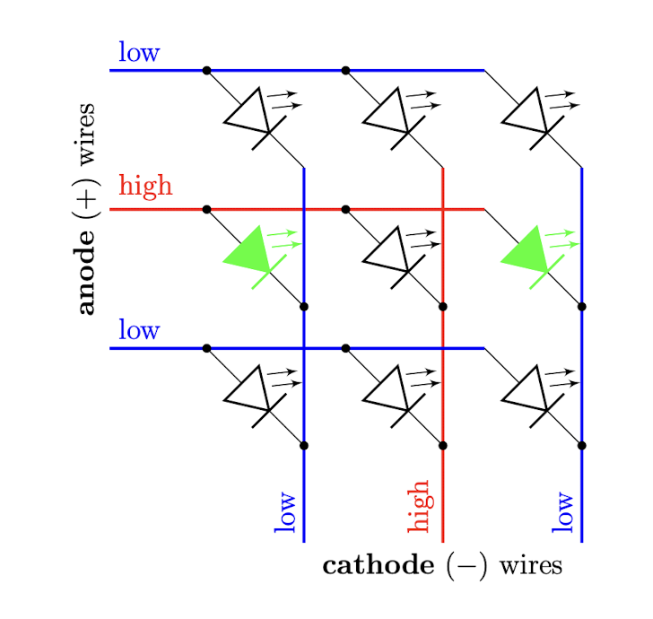
Multiplexing diagram. Courtesy: ENGR 40M Fall 2025, Stanford University
As shown in this simplified diagram, if we can manipulate the voltage along horizontal wires, we control one row at a time by setting that row's wire to high voltage (and all others to low voltage). Then, setting the ends of the vertical wires to low voltage provides enough voltage difference over those columns' LED's to run current and turn on. Where the vertical wires are set to high voltage, no current flows and the diodes remain off. Thus, we get individual control over all of the LED's in that row; flashing through the rows lets us seemingly control all LED's in the grid at the same time.
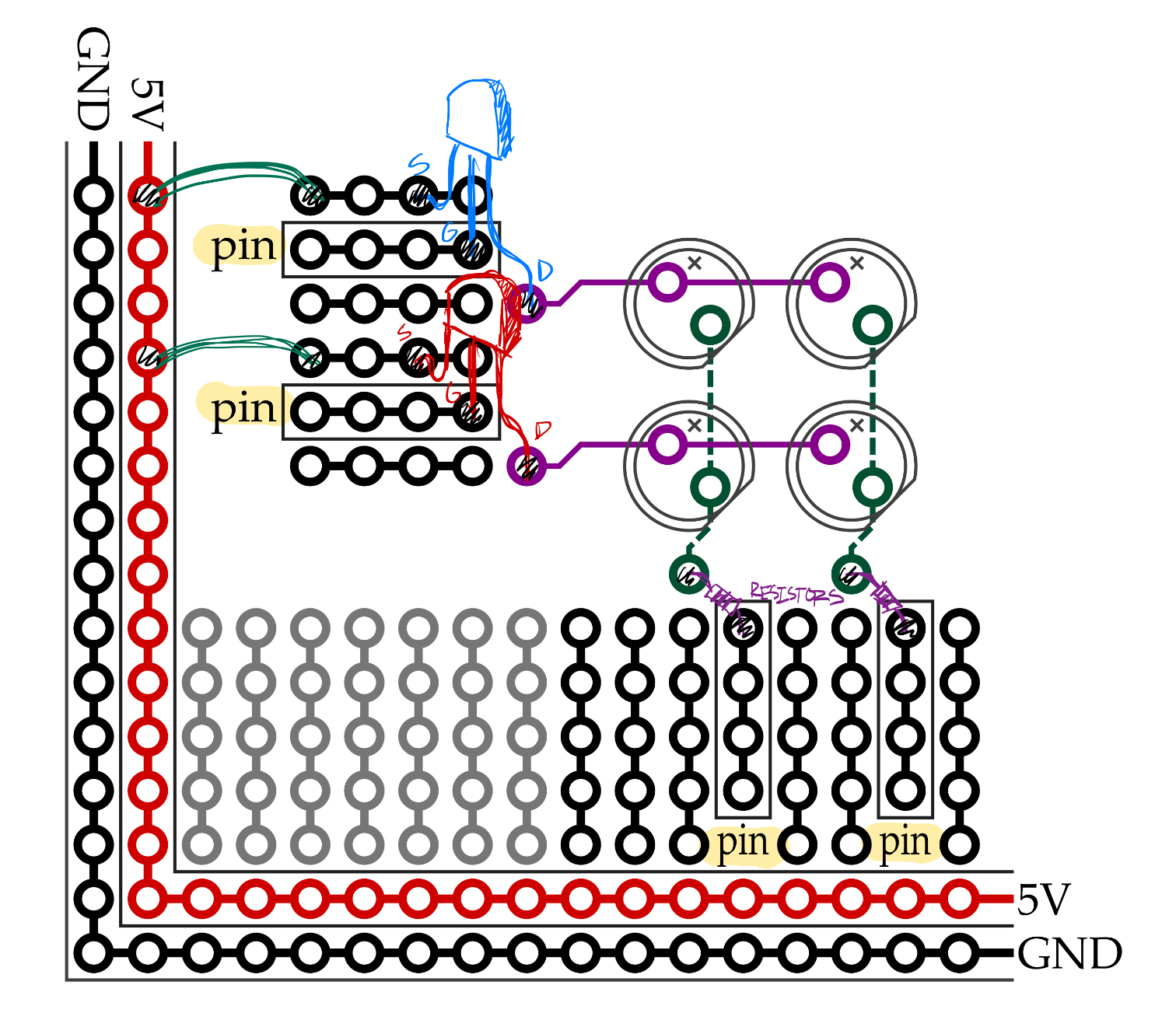
Layout. Courtesy: ENGR 40M Fall 2025, Stanford University
On the provided board, Arduino pins were connected to the gates of nMOS transistors, with all source terminals wired to the power rail. Meanwhile, each column was connected (in series with a resistor) to other Arduino pins, to be set at either VCC or GND voltage.
I chose to extend this LED grid project by including two more components: a joystick with push button for input, and an optional speaker. When I took the introductory programming course CS106B last year, I completed an assignment implementing a twelve-tone matrix in C++. I wanted to achieve a similar outcome with the LED grid, only in analog. So I wrote some Arduino and Python code to create this eight-tone matrix!
Through the project, I learned about reading potentiometers, switch debouncing, working with analog audio, and more. Unfortunately, I couldn't handle audio frequency generation directly on the Arduino, so the state of the grid must be transmitted from the Arduino to my computer, where the audio is procedurally generated and sent back to the circuit board speaker. Working with a microcontroller like Daisy Seed—as I will in the upcoming guitar pedal project—might enable implementation entirely on the circuit board itself.